|
|
Post by lefranglais on Apr 30, 2020 10:55:54 GMT
Whilst in splendid isolation I might as well start another build thread. Its an instrument I made 4 or 5 years ago and it's not a 'how to do it' it's a 'how I did it' so if anyone wants to chime in with "why did you do it that way," or "wouldn't it have been better this way?" pleas feel free. So here goes.
The ‘Ashbory’ bass wasn’t really a resounding success. Partly because it was fretless, and I decided I’m really not cut out for playing fretless (some may say that I’m not cut out for playing bass, but I wasn’t going to let that stop me), and partly because I thought that those rubbery strings wouldn’t need compensation… and they did. So although it had fret lines, they weren’t in the right place. And then, I wasn’t all that keen on the rubbery strings, etc., etc… So why would I want to make a bass ukulele? Well, for a start, Kala had started making the Ubass and a friend had one I tried and they also made fretted ones ... I was playing traditional music for dancing (barn dance, ceilidh, etc.) with a group of friends, so when I turned up for a gig and they said “they want us to follow the procession round the town and play a few tunes each time it stops”, I said “Yeah, OK, I’ll play the drum”. Then one of the group says “What you need is a small lightweight bass you can carry around and a small lightweight amp, although, where would you plug it in?” “Funny you should say that… It just so happens I already have a Roland Microcube and although you can plug it in you don’t need to because it will work for about 12 hours on 6 AA batteries; and I also happen to be thinking of making a bass ukulele” What’s more, I thought I’d found the solution to the rubbery strings. A German firm called Stevens made a bass ukulele. You don’t seem to hear much about them, probably because their bass uke costs about 3 times as much as a Kala, although they are made from solid mahogany or EIR with spruce or cedar tops, ebony bridge and fingerboard and Schaller tuners, etc. But the big difference is they don’t use the rubbery strings. They have strings specially made for them by Pyramid (who make strings for every instrument you can think of and some you’ve never even heard of) and they are silver plated copper wire wound onto nylon filament cores. Like classic guitar strings on steroids. OK, they probably don’t sound as much like a double bass as the rubbery ones, but I can put up with that. I’m not copying the Stevens shape; I actually don’t like it much, and I’m not doing a cutaway (whoever gets above the 14th fret on a bass? I never get above the 9th. As far as the construction goes, it’s more or less like the OM I made for my nephew scaled down a bit. So here goes. Of course, as it’s another instrument I’ve never made before, I had to start by making these things. I didn't have to make everything from scratch as I borrowed bits and pieces from the OM mould and bender. 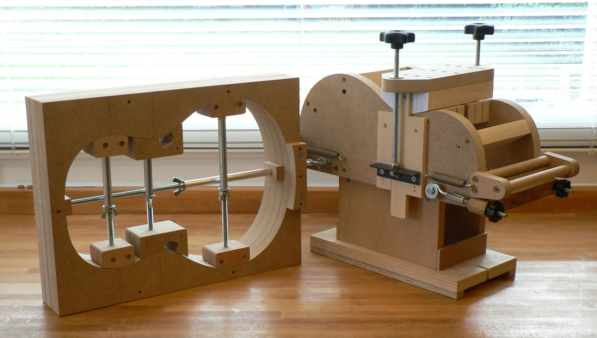
|
|
ocarolan
Global Moderator
 CURMUDGEONLY OLD GIT (leader - to join, just ask!)
Posts: 35,724  Mini-Profile Background: {"image":"","color":"c0cfe1"}
Mini-Profile Name Color: 182a3f
Mini-Profile Text Color: 733a1c
|
Post by ocarolan on Apr 30, 2020 11:06:33 GMT
This sounds very interesting! I really enjoyed playing the bass uke that davewhite made a few years ago, a fretless one. Actually the octave is useful to reach on bass, though a bit of a stretch to get there is OK! Keith |
|
|
|
Post by lefranglais on Apr 30, 2020 16:03:53 GMT
I’m not taking quite so many photos this time, but if you look at the OM thread you’ll probably see the ones I’ve missed out. I’m making it with an adjustable neck again (although slightly modified) and an access panel in the tailblock. There’s a slight snag though as I can’t get my hand through the hole in this one. I forgot to mention that the body is the same size as a baritone ukulele, so shallower than a guitar. Here’s the tail block with the disc which will become the access panel.
Here are the components of the neck block. 2 pieces of mahogany, one of them glued to a piece of birch ply.
Having drilled the holes I install the threaded inserts. They need to go down as far as the black line.
I press the insert down and turn the drill chuck by hand until it starts to screw in. Then I release the jaws of the chuck but leave it in place to act as a guide so the insert goes in straight.
After milling all the other slots, the other block of mahogany is glued on and trimmed. This forms a sort of Spanish heel.
A view from the other side.
Two recesses are milled in this block. This is to reduce the area to be sanded to fit the back while leaving enough to strengthen the joint between the neck block and the back. Then the surface in contact with the sides is sanded to the profile of the sides. This will be refined before gluing to the sides by rubbing on sandpaper stuck to the mould. 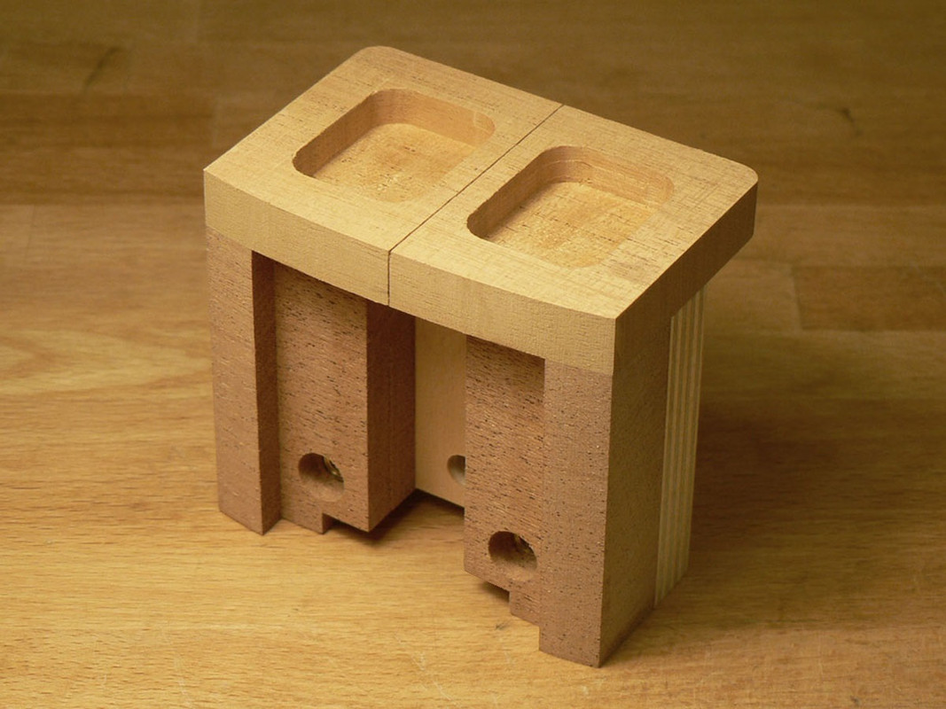
A view of the block the other way up.
Now the holes are drilled at the compound angle necessary for the tubular carbon fibre struts which help support the neck block.
The block is more or less finished. The difference between this and the OM is that I decided to make it so that the adjustment of the front-to-back neck angle (i.e. the action or string height) will be adjusted from inside the body instead of through the heel from the outside.
I forgot to say what the rest of the specs are. I had a set of East Indian rosewood and a spruce top that I bought in 1970 so I think the spruce must be European, probably German. I hadn’t used it before because the spruce had darkened a lot at the edges and had a lot of little brown spots all over it. The EIR had quite a lot of white mineral deposits which I hoped to be able to hide. I had a piece of Spanish cedar big enough to make 2 baritone ukulele necks, so I decided to use some of that, and the fingerboard and bridge will be EIR
More later.
Dave.
|
|
|
|
Post by lefranglais on May 1, 2020 9:21:31 GMT
Now I can start on the sides. First I made a template using Colin’s method. i.e. place the mould on the radius dish and chock up the tail block end of it by the difference in body depth between the tail block and the neck block. Then, with a piece of card temporarily stuck to the mould, trace a line (using a pencil lead stuck to a piece of wood) following the contour of the radius dish.
This is the side profile it gave me.
I had one of those photography lapses here, and didn’t take any photos for a while. I get involved with what I’m doing and forget about photos. So now, the sides have been thicknessed, profiled and bent, trimmed to length and placed in the mould, and the neck and tail blocks glued in place. That makes it sound a lot quicker than it was.
The neck bock is made with some surplus thickness to allow for the curvature of the back and the difference in depth between neck block and tail block. Some of that gets planed off here.
Now the carbon fibre struts are installed. I have to glue the struts into the neck block and buttresses and the buttresses to the sides at the same time. The tubes are glued into the neck block using epoxy and the buttresses glued to the sides with fish glue. 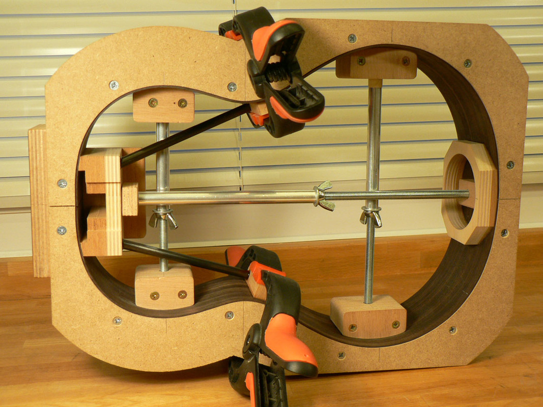
I decided to make laminated solid linings so here’s another jig I had to make to glue them up.
Here’s what came out of it. The jig’s a bit more complicated that other people’s, but I find it much easier to use in 3 pieces with the outer parts hinged and the slats on either side so that it’s more or less self-aligning.
Here’s one of those ‘forest of clothes pegs’ photos. Two of the laminated linings are being glued in place after trimming to length but, of course, you can’t see them. The clothes pegs’ clamping force is augmented with rubber bands. Don’t ask me what the black dots are for; I’ve been trying to remember myself.
Now you can se a bit of one of the linings. I notched them so that the buttresses are let into them and chamfered the end of the buttresses just to make them look slightly les clunky.
The linings were glued in slightly proud of the sides, and then most of the surplus taken off with a spokeshave. I don’t know what the correct way is to use a spokeshave. In photos, people always same to be pulling them towards themselves as one does with a drawknife. That just feels wrong to me; and the tool seems to be designed for pushing with two indents for the thumbs, so that’s what I do.
After that, a bus-driving session on the radius dish to get the linings and end blocks flush with the sides.
|
|
|
|
Post by lefranglais on May 4, 2020 10:12:26 GMT
Before moving on to back and front, I have to make the access panel. I should have taken a few more photos but… In this not-very-explicit photo the end graft has been made and is held in place on the plywood disc by the brass dowel. While it’s there, two pieces of maple are being glued to the disc on either side of it. 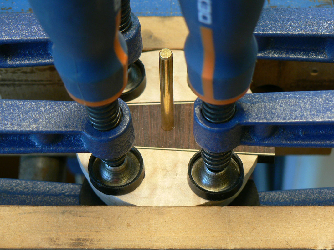
Once the glue is dry I can take the wedge out and the maple pieces are sanded circular and to the required diameter. So now the bits look like this. 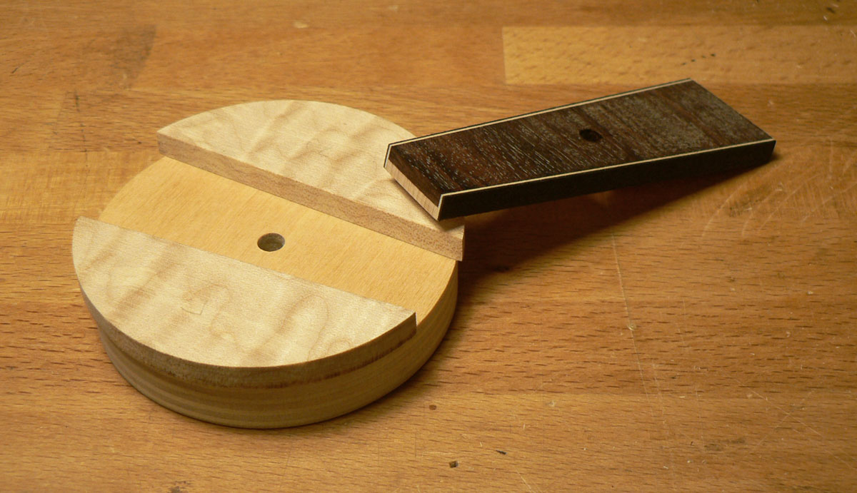
Then a couple of bits of veneer are glued onto the maple.
I now need to cut the hole in the sides for the panel. The disc fixed to the rectangular panel is fitted into the tail block and held in place with double sided tape. This serves to hold the sides in the vice and has a central brass pin on which the circle cutter will rotate as shown in the next photo.
A makeshift platform to support the circle cutter is fixed to the sides, again with double sided tape.
The hole is cut so that the panel just fits into it.
Now I can glue the wedge into the panel. I then fit the panel into the hole, align the wedge (the ‘right’ way up this time) and scribe either side of it to mark where to cut the sides.
and here is the panel in place.
Of course the panel is flat and the lower bout is curved. To be able to plane and sand the curve onto it, it has to be firmly held in place. So I have to make the support bracket which fits inside.
Now I can make some nice shavings.
Until it looks like this.
|
|
ocarolan
Global Moderator
 CURMUDGEONLY OLD GIT (leader - to join, just ask!)
Posts: 35,724  Mini-Profile Background: {"image":"","color":"c0cfe1"}
Mini-Profile Name Color: 182a3f
Mini-Profile Text Color: 733a1c
|
Post by ocarolan on May 4, 2020 11:07:44 GMT
What a fine job that end panel is!  Keith |
|
|
|
Post by Vinny on May 4, 2020 11:43:30 GMT
Very impressive.
|
|
|
|
Post by lefranglais on May 9, 2020 15:59:29 GMT
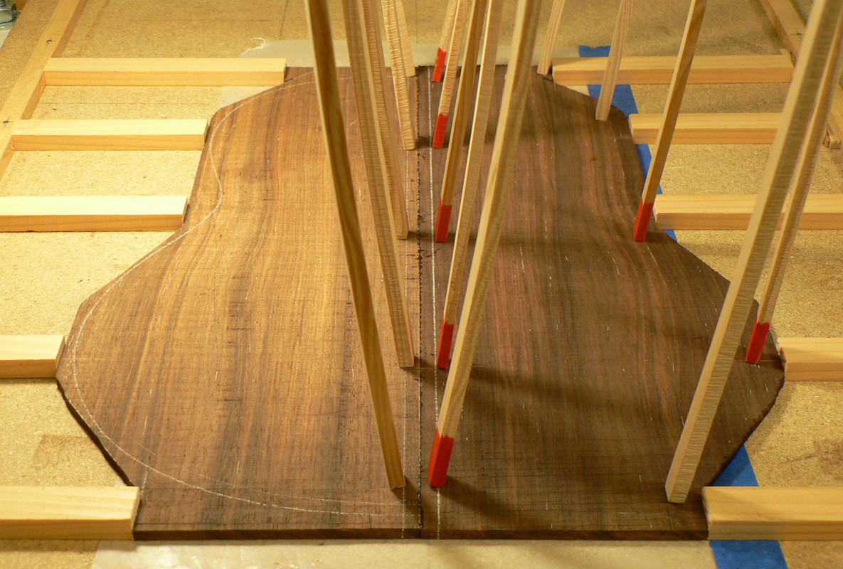
That’s the sides finished so I can start on the back and front. This is an EIR back set that was big enough for a Dreadnought, so I cut enough out of it for the back and the rest will serve for something else. I like this method of gluing the back as the two edges are held in alignment by the go-bars. You can just see the wedges on the right that force the two halves together. The colour on the left shows what happens to rosewood when it’s been exposed to the light for 45 years. You can also see some of the white mineral inclusions I was talking about.
The centre back-strip being glued in. I like to hold the back down firmly in the radius dish while the back-strip and the other braces are glued in. It helps to keep the curve of the back. Look at the difference in colour now that the back has been reduced to finished thickness.
Gluing some of the braces.
The last two braces being glued. The others have been shaped and sanded.
The dark colour at the edges of the spruce and the brown spots were luckily on the surface so after joining and sanding to thickness I inlay the rosette. This is an off-cut of quilted maple from the last electric bass I made. It doesn’t have to be a perfect fit as it will have an inner and outer black-white-black veneer ring inlaid after the glue sets.
I find it much easier to glue up the veneers into a circle before inlaying them. The diameter doesn’t have to be exact as it will bend easily to fit in the groove.
The veneers have been inlaid and the hole is being cut out.
I swear the black veneer was the same thickness as the white, so why does it look twice as thick now?
Front braces being glued. In case you’re wondering what the two arrows are for, I mask the front when gluing braces. It seems that the front has some run-out and if I pull the masking tape off in the wrong direction it lifts the fibres of the spruce. So the arrows are to remind me in which direction to pull off the tape.
I’ve been looking for the photo of the front finished. As well as what you can see above, it has a bridge plate with three small fan braces below it and two little finger braces, but I must have had another ‘senior moment’ and forgot to take it. Sorry about that.
|
|
|
|
Post by lefranglais on May 10, 2020 15:16:44 GMT
With front and back finished I can glue them to the sides, starting with the back. The sides were first carefully positioned on the back and the small locating blocks glued on.
Stuck a label in.
And then glued the top on.
I decided to use the same wood as the sides for the bindings and as I’d cut the sides to their profiled shape, I cut profiled bindings for the back. It made them a lot easier to fit. Straight ones are OK for the front.
No in-process photos, but here’s the box bound.
|
|
|
|
Post by lefranglais on May 12, 2020 8:03:20 GMT
On to the neck. Here are the bits glued together. It’s Spanish cedar and smells nice but I think it makes me a bit itchy. The holes are for dowel pins to keep the bits from sliding around while gluing. They are in areas that will be cut off later. 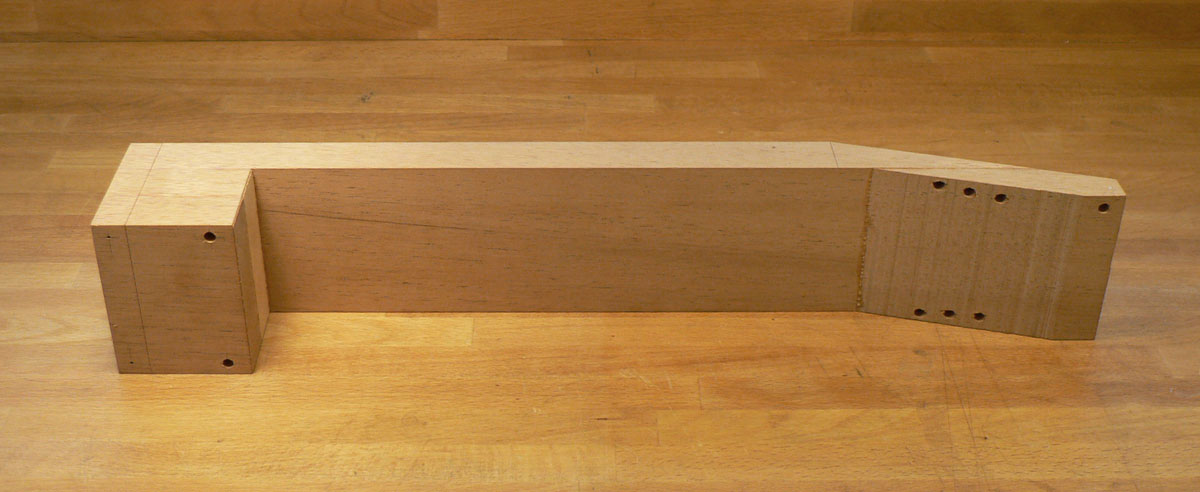
The heel has two cross-grained maple strips glued in to strengthen it where the barrel bolts will be.
The tenon was roughed out on the band saw and finished on the milling machine. Then the holes were drilled for the barrel bolt ‘barrels’. 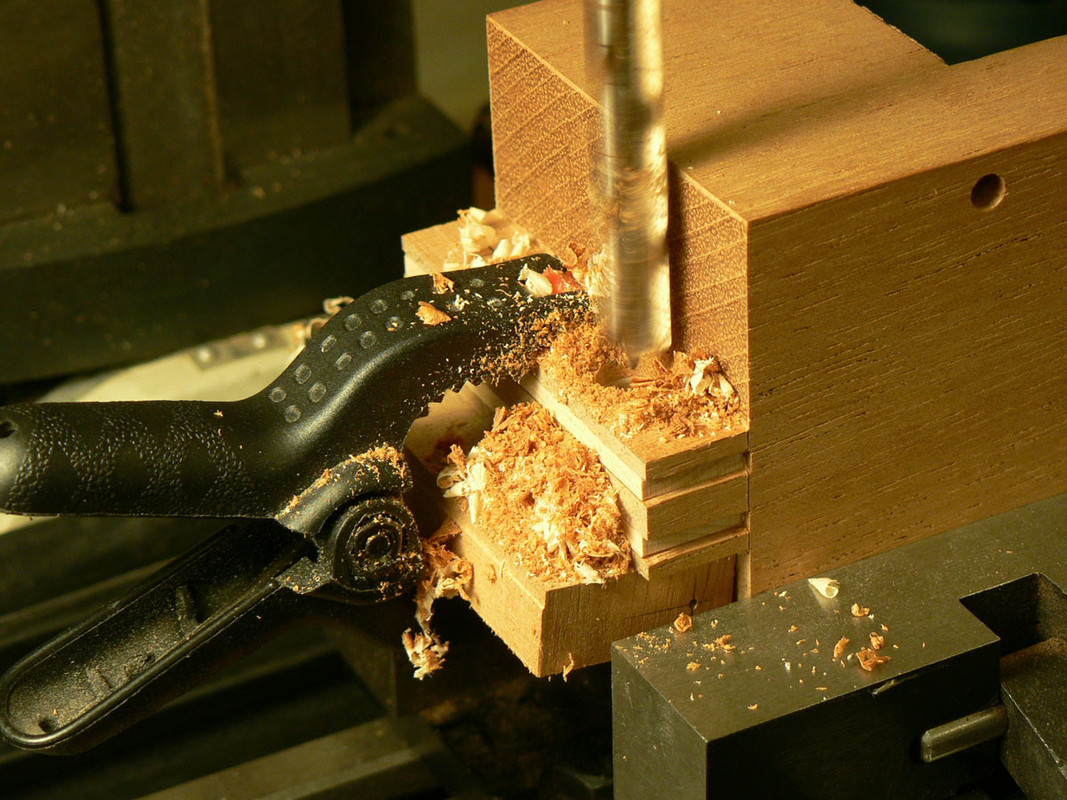
And holes for the bolts. Drilling through the dowel gives a nice clean intersection of the two holes.
And this is how they fit.
Now comes the slightly tricky job of drilling two accurately positioned holes for the brass plugs which have to line up as precisely as possible with the two Allen setscrews in the neck block. I made a plywood drilling jig on the milling machine, so the holes are accurately positioned. This is clamped to the neck tenon. The brass rod was fixed in the drill chuck and lowered into one of the holes, and the neck heel clamped to the drill-press table. Then the brass rod is exchanged for the drill bit and the hole drilled.
Here are the two brass plugs that will be glued in.
And here they are in position but NOT GLUED. Why not? Because if I glue them in I won’t be able to get the barrel nut in its hole. (DAMHIKT)
The heel is strengthened with two pieces of CF tube. Here they are before being glued in with epoxy.
Cutting the recess for the neck extension wich supports the fingerboard.
Gluing in the neck extension.
Neck extension glued in and trimmed flush with the neck. Although the neck is cedar and the extension is mahogany, they look almost the same.
To be continued.
Dave.
|
|
|
|
Post by lefranglais on May 13, 2020 12:26:56 GMT
Here’s the neck blank with a piece of MDF cut to exactly the same width as the neck.
The fingerboard is attached centrally to the MDF with double sided tape. This means I can run the fingerboard and the neck blank over the router table and get perfectly aligned slots.
Here are the slots all routed. This neck is too short and stubby for a truss rod, but I thought it wouldn’t hurt to add a bit of carbon fibre to the mix, so here it is.
A simple little jig to keep the side dots aligned on the fingerboard.
The 4 pins keeping the head plate aligned while gluing, are in holes that will be enlarged for the tuning machines.
After taking some of the surplus off on the bandsaw, I take the head down to final thickness on the spindle sander.
Gluing on the back-strap veneer.
Back-strap glued.
The headstock is now roughly cut out with the jig-saw….
…and finished using a template on the router table.
|
|
olsk
Strummer
 
Posts: 20
|
Post by olsk on May 13, 2020 18:10:07 GMT
Inspiring precision! That neck joint is a work of art - thanks for sharing
|
|
|
|
Post by lefranglais on Nov 23, 2020 21:38:02 GMT
Apologies to anyone who followed this thread and wondered why it stopped. I'm wondering myself now. I suppose it was Covid and life and senior moments, etc. and I just forgot about it. Tends to happen to me more and more these days. Anyway, there isn't a lot more to tell. The next thing was routing the ledges for the headstock binding. I’ve always found it difficultwith the normal Stewmac router base. I always manage to let it wobble at some point and cut a little divot, so I made this larger one which made it much easier.
I was quite pleased with the mitres on this one. I never know how good they are until I’ve scraped the bindings flush with the headplate.
Then it was gluing the fingerboard on.
The fingerboard being flat makes it easy to route the neck flush with the fingerboard.
The heel, which wasn’t trimmed flush by the router was trimmed with a hand plane.
To carve the neck, I draw a section in CAD at its narrowest and widest point, which gives me the dimensions of facets at 45° and then smaller ones at 22.5° to the first ones. I can’t transfer this precisely onto the neck of course; I just measure them as closely as I can. I start off using a microplane cutting notches up to the facet lines.
I join these up, by first chiselling the bulk off…
…and then spokeshaving…
…which gets it to this point. I then do the same thing with the 4 smaller facets.
After that, it’s a bit of work with a sanding board and then ‘shoe-shining’ with varying grits of cloth-backed abrasive.
The neck profile is blended into the headstock and the heel using chisels, files and sanding sticks.
For some reason, the photography fell by the wayside at this point, so there aren’t any more photos although there wasn’t a lot left to show. Finished photos next.
|
|
garynava
Luthier / Guitar Maker
Posts: 460  My main instrument is: Stanley No.5
|
Post by garynava on Nov 25, 2020 15:43:01 GMT
Super clean work! Hats off to you!
Cheers Gary
|
|
colins
Luthier / Guitar Maker
Posts: 2,397  Member is Online
|
Post by colins on Nov 25, 2020 17:00:03 GMT
Exquisite workmanship as always David. Say hello to Cathi from me.
|
|




 Jo whoever he is.


